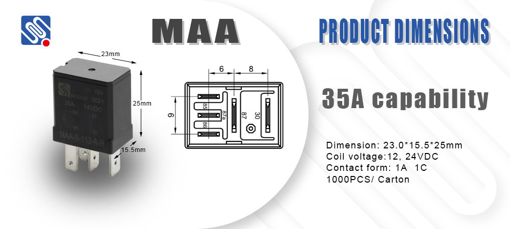
在继电器电路图中,通常会包含以下几个主要部分:

继电器的线圈(Coil):通过电流激活继电器。通常在图中用两个并排的符号表示,表示电流通过线圈时,继电器被激活。 触点(Contacts):继电器的触点可以是常开(NO)或者常闭(NC)触点。当继电器线圈通电时,常开触点闭合,常闭触点打开。触点通常用于控制其他电路。 电源(Power Supply):供电源连接到继电器电路中,通常会标出电源的电压和电流。 负载(Load):继电器可以用来控制负载,如电动机、灯泡等。在电路图中,负载一般与继电器触点连接。 控制电路(Control Circuit):继电器的控制部分,用于启动继电器的动作,通常由按钮、开关、传感器等组成。 继电器电路图可以应用在自动化控制系统中,如开关控制、定时器、保护电路、报警系统等。 如果你有具体的继电器电路图或应用场景,可以提供更多详细信息,我可以帮你分析或解释。
帮我写一篇关于Relay electrical diagram的800字英文原创文章,并在文章前面配上一个标题,并在标题里面包含Relay electrical diagram Understanding the Relay Electrical Diagram: Principles and Applications A relay electrical diagram is an essential tool used in the field of electrical engineering to represent the operation and connections of a relay in a circuit. Relays play a crucial role in controlling electrical circuits by using a small amount of power to switch larger amounts of electrical current. In this article, we will explore the basics of a relay electrical diagram, its components, and common applications.
Leave a Reply